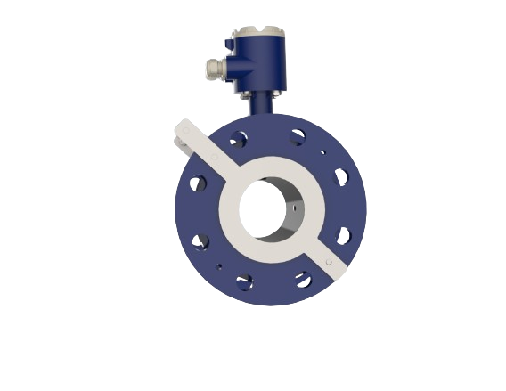
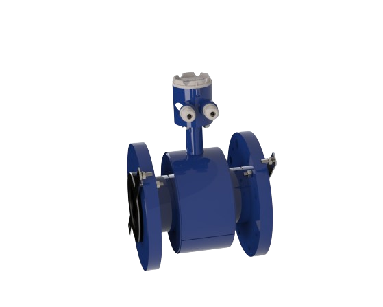
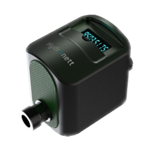
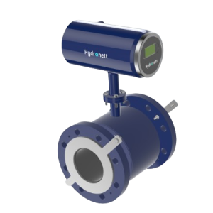
Description
- Accuracy +/- 0.5%
- Working range 0.1 m/s to 5 m/s
- Low flow as low 0.01m/s
- Open / Short Coil Alarms
- Low Flow / High Flow Alarms
- Built-in Empty pipe detection
- Communication Options GSM/GPRS
- NbIoT, Wireless Mesh
- IP68 Resistance
- Built in data logger
- Partial pipe detection
- Wireless communication via Bluetooth
- IP 68
- GSM, GPRS, NBIoT
- RS 45, pulse output
- Paid access to hydro world app & Access to BlueNett HES
Working Principle
-
Faraday’s law of principle
Faraday’s law of electromagnetic induction (referred to as Faraday’s law) is a basic law of electromagnetism predicting how a magnetic field will interact with an electric circuit to produce an electromotive force (EMF). This phenomenon is known as electromagnetic induction.
-
Principle Of operation
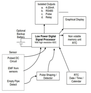
The operation of a magnetic Flow meter or Mag meter is based upon Faraday’s law, which states that the voltage induced across any conductor as it moves at right angles through a magnetic field is proportional to the velocity of that conductor. Here water is the moving conductor. A uniform magnetic field is generated by two coils and forcing a constant current through the coil. The magnetic field is in a transverse direction to the flow of water. Since movement of water (corresponding to a moving conductor) generates an EMF transverse to the magnetic field and direction of flow. This EMF is picked up by three sensors which are then amplified by high sensitivity amplifiers. The amplified signal is then converted using high resolution ADC which is then sampled and digitally filtered using a digital signal processor to convert to flow readings.
Hydro master Series Features
Performance Features
| Working range | 0.1 m/s to 5 m/s |
| Alarms | Open / Short Coil Alarms |
| Alarms | Low Flow / High Flow Alarms |
| Error Information | Built-in Empty pipe detection, Coil short, RTC failure, Memory Fail, Excess flow rate |
Operational features
- Suitable For both Vertical & Horizontal orientation
- 128 x 64 graphical backlit display
- Pulsed DC operation
- Programmable digital filters
- Inbuilt RTC and non-volatile memory to save periodic flow record
- Batch Control Operation
- Batch start stop from RS485 commands
- 4-20mA input for partial flow measurement
Operating Temperatures
- Maximum Operating Temperature used Rubber Lining (NBR) - 55 ° C
- Maximum Operating Temperature used PTFE Lining - 160 ° C.
Electrical Parameters
| Power supply | 90-270V AC with continuous protection up to 440VAC, 50Hz |
| Signal Input | Induced EMF picked up by sensors in the flow tube |
| Coil Drive Output | Constant Current / Frequency |
| Display | 128×64 graphical LCD display |
| Operations | Using 4 keys |
| Analog Output | Isolated 4-20mA |
| Digital Output | Pulse. Isolated open collector output |
| Communication | Isolated RS485 / MODBUS protocol |
| Isolation Voltage | 1.5KV |
| Relay Outputs | 2 Maximum* |
| Relay Rating | 5A at 220V AC linear load |
| Programmable Setpoints | 4 |
| Resistance | IP68 |
Environmental Features
| Max. Operating Temperature: | 55 °C |
| Storage Temperature | 0 – 80 °C |
| Humidity | 0 – 80% non-condensing |
Flow parameters
| Flow Rate | m3/hr |
| Forward / Reverse | Indicated on Screen |
| Total Flow | Forward Total Flow Reverse Total Flow |
| Induced EMF | Displayed in diagnostic Screen only (not standard) |
| Date/ Time | From Inbuilt RTC |
| Flow K Factor | 0.0001 to 9.9999 |
| Stored Parameters | Date/time, Rate of flow, forward total flow, reverse total flow, tamper information & periodic stored Records |
Communication & memory Features
| Serial Communication | RS485 / MODBUS Protocol |
| GSM/GPRS Communication | Facility to add GSM Modem |
| GSM/GPRS Communication Method | GPRS/TCPIP to static IP server, SMS to programmed numbers, FTP to server |
| Memory | 32K bytes Maximum |
| No of records stored | 2500 maximum |
| Record Storage Interval | Programmable Minimum: 1 Minute Maximum: 1 Day |
| Memory Type | Non-Volatile memory |
| Memory Retention | 100 Years |
Hydromaster internal block diagram
